Geopsy: Filter
Filter is a Basic signal processing tool in the Waveform menu and a tab in the advanced signal processing tools. In the first case, it applies a filter to the signals in the active signal viewer. In the second case, it applies a filter to the active signals to select appropriate windows for the tool computation.
In Waveform menu, by clicking on Filter, a pop-up window appears to customize the filter. In that case "Filter" modifies the temporary signals in the active viewer. In an advanced tools like H/V tool, checking the "Anti-triggering on filtered signals" checkbox (Tab "Time" sub-tab "General") let the user select windows only based on the chosen frequency band. In that case the filter is not applied for the computation but only for the window selection.
Filter parameters
The basic parameters for the filter is the type of filter:
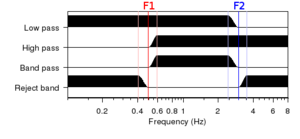
- "Low pass" filters the frequencies above a given value.
- "High pass" filters the frequencies below a given value.
- "Band pass" filters the frequencies out of a given frequency range.
- "Band reject" filters the frequencies inside a given frequency range.
The cut-off frequency(ies) of the filter should be provided in the neighboring text box(es). All the values are in Hertz.
Filter method
Two filters are currently implemented in Geopsy:
- "Butterworth filter" is linear continuous-time filter with a maximally flat frequency response. By default, the filter is applied in both directions that makes it non-outphasing but not causal (filter output depends also on inputs in time). The "Causal" check box ensures the filter will be causal (filter output depends only on past and present inputs, so that no artificial effect can be created before the arrival of a propagating wave, for example) by an application in only one direction. However it does not conserve the phase of the signal (outphasing filter). This option should therefore not be used for processing based on phase information, e.g. array processing The "Order" of the filter defines the number of data points used for the computation of a single filtered point. Low order affect less the signal but make the filter less efficient. High orders make the filter more efficient but may affect more the signal. The default value is 2.
- "Cosine Taper" is a linear finite impulse response (FIR) filter based on the Cosine tapering window. This filter is non-outphasing but perfectly non-causal. The "Width" parameter gives the width, relatively to the cut-off frequency of the slope of the filter (see Figure). Default value is 0.1 (10% of the cut-off frequency).
See also:
