Difference between revisions of "Dinver: dinverdc"
| Line 34: | Line 34: | ||
[[Image:Dinverdc_parameter_panel.png|thumb|center|800px|Parameter panel]] | [[Image:Dinverdc_parameter_panel.png|thumb|center|800px|Parameter panel]] | ||
| − | If this panel does not appear, you can show it with menu [[Dinver: | + | If this panel does not appear, you can show it with menu [[Dinver:Menus:Tools|Tools]]. |
It defines the parameters of the ground structure. It is organized in various independent profiles. Layering may be different in each profile as shown in above figure. | It defines the parameters of the ground structure. It is organized in various independent profiles. Layering may be different in each profile as shown in above figure. | ||
Revision as of 21:00, 26 November 2008
dinverdc is an external plugin for dinver. It implements forward computations for surface waves and refraction analysis. It handles phase and/or group dispersion curves for Rayleigh and/or Love waves. Additionally, it computes refraction travel times for Vp and/or Vs.
Invoking dinverdc
Upon dinver startup, select the Surface Wave Inversion module by checking the corresponding check box. See Dinver plugins for more details, especially if Surface Wave Inversion module does not appear by default.
The module selection can be set also directly in the command line invoking dinver:
dinver -i DispersionCurve
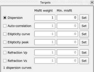
Target panel
If this panel does not appear, you can show it with menu Tools. it lets you select the type of curve to fit during the inversion. Available types are:
- dispersion curves
- auto-correlation curves
- ellipticity curves
- ellipticity peak frequency
- refraction travel times for Vp
- refraction travel times for Vs
Several types can be checked at the same time. In this case, a global misfit value is computed by a weighted sum of the individual misfits. The weights can be adjusted with Misfit weight values. The weights are normalized by the sum of all weights of the selected types.
Min. misfit is an alternative way for computing misfits. Usually misfits include a sum of squared differences between observed data and calculated ones. The difference is normalized by the variance (if it is available) or by the observed value. Additionally, the normalized difference can be forced to a minimum threshold (Min. misfit). See Minimum misfit for more details.
To load or set the curves click on the corresponding Set button.
Parameter panel
If this panel does not appear, you can show it with menu Tools.
It defines the parameters of the ground structure. It is organized in various independent profiles. Layering may be different in each profile as shown in above figure.
- Compressional wave velocity profile
- Poisson's ratio profile
- Shear wave velocity profile
- Density
- Pitch (for refraction only)


