Difference between revisions of "Geopsy: H/V and Spectrum Toolboxes: Processing Tab"
(→Use) |
|||
| Line 4: | Line 4: | ||
== Use == | == Use == | ||
| − | This toolbox tab contains the smoothing and taper parameters | + | This toolbox tab contains the smoothing and taper parameters and the way the horizontal components are processed to compute the H/V spectral ratio, described in two sections: |
*the Parameters section | *the Parameters section | ||
| Line 12: | Line 12: | ||
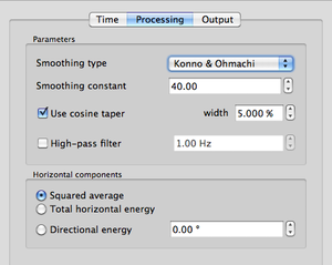
[[Image:HV_SPEC_toolb_process.png|thumb|center|300px|''Processing'' tab for smoothing parameters and horizontal components processing in H/V computing]] | [[Image:HV_SPEC_toolb_process.png|thumb|center|300px|''Processing'' tab for smoothing parameters and horizontal components processing in H/V computing]] | ||
| − | |||
| − | |||
== Parameters section == | == Parameters section == | ||
Revision as of 13:06, 10 January 2013
Contents
Use
This toolbox tab contains the smoothing and taper parameters and the way the horizontal components are processed to compute the H/V spectral ratio, described in two sections:
- the Parameters section
- the Horizontal components section (For H/V tool only)
Parameters section
This section is divided in three parts:
Smoothing
Type of smoothing applied to the windows. During the computing of H/V or Spectrum, the Fourier spectra can be smoothed (it is strongly recommended) in the goal to clarify the global aspect of the curves.
For the Spectrum computation, the Fourier spectrum from each selected time window is smoothed and then the averaged curve is computed.
For the H/V computation, the horizontal Fourier spectra (NS and EW) are first combined and then the smoothing is applied on the merged horizontal Fourier spectrum and on the vertical Fourier spectrum.
Four smoothing methods are evailable:
- Konno and Ohmachi[1] smoothing. This smoothing use a constant bandwidth in a logarithmic scale and is strongly recommended because this smoothing function preserves the different number of points at low and high frequency. This smoothing is controlled by a smoothing constant varying in-between 0 and 100. A constant of 0 gives a very strong smoothing, when a constant of 100 a very soft smoothing, more details;
- Constant smoothing. This smoothing function has a triangular shape centered on the current frequency and its width is equal to "Band width" given by the user. This band width varies from 0 (soft smoothing) to 100 (strong smoothing);
- Proportional smoothing. This smoothing function has a triangular shape and its width depends upon the current frequency. The half width is defined by percentage*frequency. The value of "percentage" cannot be greater or equal to 100% (strong smoothing).
- No smoothing. This can be sometime useful to have a rough idea about Fourier spectra;
The Smoothing constant spin box is used to give the smoothing constant value.
Taper
Check the box to apply a cosine taper on both sides of the selected time windows.
A taper is used to minimize the border effects due to the extraction of a window so as to improve its properties in the frequency domain. The use of a taper is strongly recommended so as to avoid the creation of spurious frequencies.
The taper width is adjusted in the spin box.
Filter
When the box is checked a high-pass filter is applied along the entire record of each component before selecting the stable time windows. This procedure is used to avoid spurious frequencies due to the effect of a strong low frequency content.
Checking this option is recommended when the signal has a strong low frequency content with respect to the frequency of interest, e.g. shallow site next to a shore line, or recording under windy condition. In such case, cutting the signal into short time windows may strongly distort the spectrum, and even using the minimum window length criteria according to the SESAME guidelines [2] (i.e. 10 times the corresponding period for the minimum frequency of interest) may not be enough to ensure a reliable H/V estimation.
This option should be used with caution. As the signal is high-pass filtered, the results below the chosen cut-off frequency could be somewhat flaky, and the cut-off frequency must be much lower than the frequency of interest.
Horizontal components section (available only in the H/V toolbox)
The H spectrum of the H/V spectral ratio is obtained by combining the N-S and E-W components of the signal.
Three different combinations are available:
- Squared average
- Total horizontal energy
- Directional energy
Squared average
In each window, the horizontal spectrum is computed by a combination of the N-S and E-W components using the formula
Total horizontal energy
In each window, the horizontal spectrum is computed by a combination of the N-S and E-W components using the formula
Directional energy
H/V is calculated along a given direction (0° is the North direction and 90° the East direction). The N-S and E-W signals are projected onto the chosen direction.
H/V is computed in the direction entered in the spin box.
References
- ↑ Konno K. and T. Ohmachi, 1998. Ground motion characteristics estimated from spectral ratio between horizontal and vertical components of microtremors. Bull. seism. Soc. Am., 88-1, 228-241.
- ↑ Guidelines for the implementation of the H/V spectral ratio technique on ambient vibrations measurements, processing and interpretation, [1], 62 pages, April 2005


